
ISO 10218:2025 and the New Era of Robot Safety Standards: What Every Integrator Needs to Know
If you have been deploying collaborative robots under the 2011 edition of ISO 10218 with ISO/TS 15066 as the supplementary guidance document, the 2025 revision is not a version bump you can file away and revisit later. The structural change is significant enough that applications currently in production require review, and applications in design need to be built against a different normative baseline than they were 18 months ago.
ISO/TS 15066's collaborative application content has become normative within ISO 10218-2:2025, replacing the term 'collaborative robot' with 'collaborative application,' and mandatory physical force measurement is now required for Power and Force Limiting validation instead of being an optional requirement. Getting those three changes wrong in a compliance argument is how you end up rebuilding a validation package after the notified body flags it.
The Standards Consolidation: What Actually Changed Architecturally
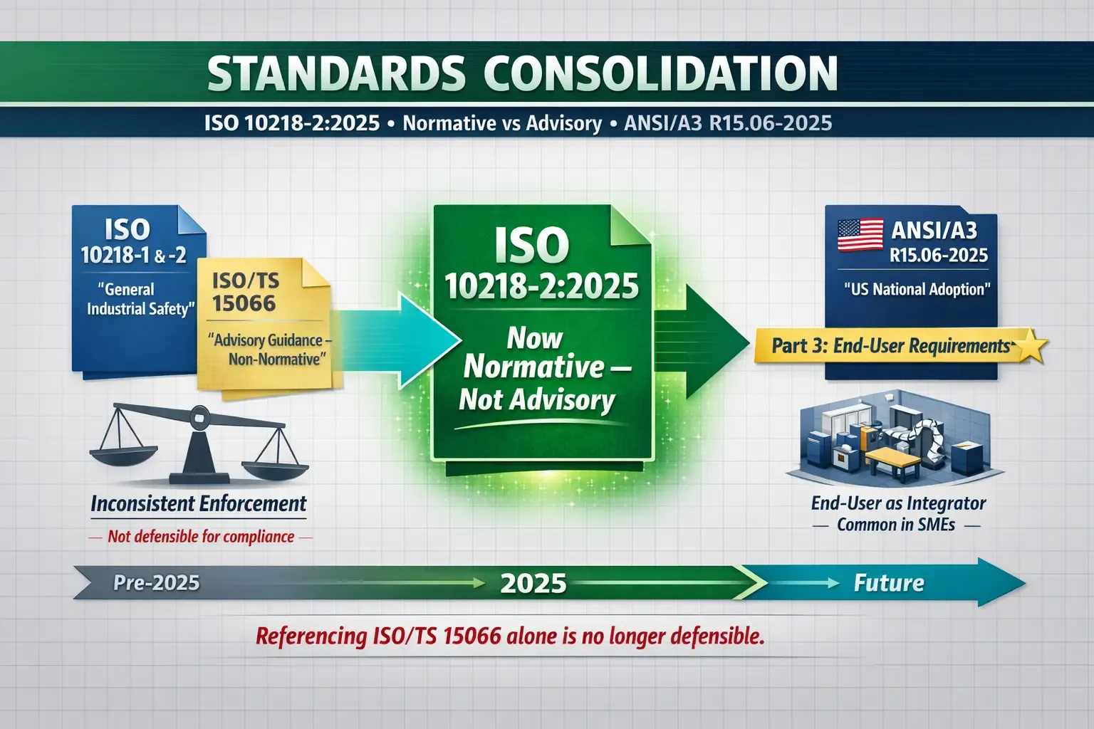
The robotics industry has been relying on a two-document framework, with ISO 10218-1 and -2 defining safety standards for general industrial robots, while ISO/TS 15066 primarily serves as the reference for collaborative operations. This advisory status introduced an ambiguity in how companies could interpret and comply with the standard's guidelines. Different notified bodies and market surveillance authorities interpreted "advisory guidance" with different degrees of strictness, producing inconsistent enforcement outcomes.
ISO 10218-2:2025 closes that ambiguity by absorbing ISO/TS 15066's collaborative content into the main standard as normative requirements. Biomechanical limits for human-robot contact, the detailed requirements for each collaborative operating mode, and the validation methodology for Power and Force Limiting are now normatively required by the standard rather than recommended by a guidance document. ISO/TS 15066 technically still exists in publication catalogs and is flagged for its own future revision, but for compliance purposes, the operative document is now ISO 10218-2:2025. A sole reliance on ISO/TS 15066 for compliance is no longer defensible.
By adopting the ANSI/A3 R15.06-2025 standard, the U.S. reinforces its commitment to national consistency, thanks to recent ISO updates. The US version adds a third part covering end-user requirements that has no direct ISO 10218 counterpart, which matters specifically for end users who are also acting as their own integrators, which is the common scenario in SME cobot deployments where the purchasing organization also designs and validates the cell.
The Application-Safety Principle: Why "Cobot" Is the Wrong Mental Model
The terminology shift from "collaborative robot" to "collaborative application" is the conceptual change that has the most practical consequence for how organizations approach procurement and compliance.
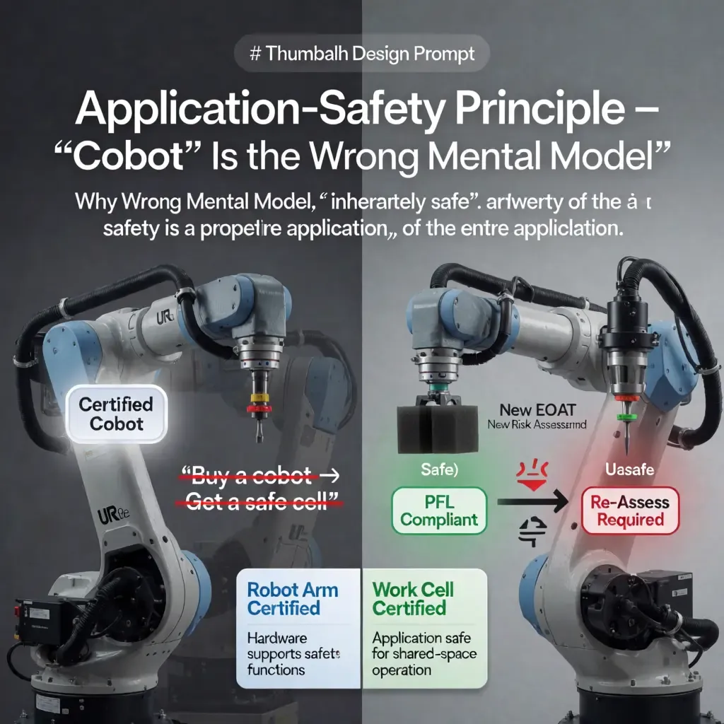
Marketing language around cobots has consistently implied that safety is a property the hardware possesses independently, that buying a certified cobot means buying a safe cobot. Under the 2025 standard, solo operation is no longer justified as a standalone aspect of robot safety and collaboration. For a thorough comprehension, it's essential to assess all components of the application in unison, including the robot arm, end-of-arm tooling, workpiece, programmed trajectory, and cell layout.
The practical implication is concrete. A Universal Robots UR10e running a soft foam block through a slow pick-and-place cycle with adequate force limiting enabled may be a fully compliant PFL collaborative application. Install a sharp deburring tool on the same robot, increase speed to meet cycle time, and you have a different application entirely, one that requires a completely new risk assessment regardless of the underlying robot's collaborative capability certification. Any time the EOAT changes, the workpiece changes, or the speed profile changes materially, the application must be re-assessed as a new application rather than treated as a minor modification of a previously validated one.
This also resolves the most common compliance error in the field: purchasing a robot that a manufacturer has certified as capable of supporting collaborative technologies, then treating that arm certification as equivalent to a certified work cell. The manufacturer ensures compliance with relevant safety standards through hardware-level integration of critical safety functions. In most cases, the organization overseeing the integration takes on the responsibility of ensuring the final application meets safety standards for shared spaces. Conflating these two distinct certifications is where liability exposure accumulates.
A comprehensive analysis of collaborative modes requires dissecting their technical fundamentals.
According to ISO 10218-2:2025, there are four standardized collaboration methods that can be used on their own or blended together within a specific application.
Safety-Rated Monitored Standstill
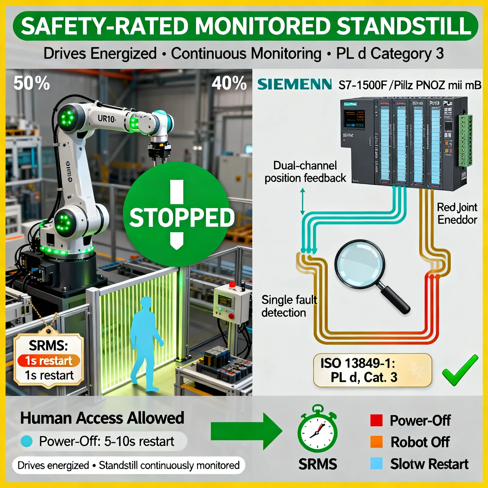
Clearance is now granted for safe access into the work zone, following a complete halt by the robot. Critically, the robot remains powered with drives energized; the standstill condition is monitored continuously by safety-rated monitoring functions rather than by removing power. The practical advantage is faster restart after the human exits the zone compared to a full power-off cycle, which matters in applications where frequent human access, for part loading or quality inspection, would cause unacceptable productivity loss if every entry required a full stop-and-restart sequence.
In order to meet safety standards outlined in the ISO 13849-1 guidelines, system manufacturers, such as those utilizing Siemens S7-1500F and Pilz PNOZ multi mB, must ensure strict adherence to Category 3 PL d requirements during standstill periods, when diagnostic capabilities can detect isolated faults before the system transitions into an unsafe state. That architecture requirement means single-channel standstill detection is not sufficient; the safety circuit needs redundant position monitoring paths.
Hand Guiding
The robot arm is controlled manually by the operator using a handheld interface, with movement restricted to direct guidance and reduced speed. Common use cases are lead-through programming in cells where the operator teaches the robot waypoints by physically moving it, and power-assisted material handling where the robot carries the weight of a heavy fixture while the operator controls the positioning. The standard's requirements for the guiding device, specific enabling button design to ensure sustained intentional operator input rather than accidental activation, directly affect the ergonomics and operator fatigue profile of this mode in sustained production use.
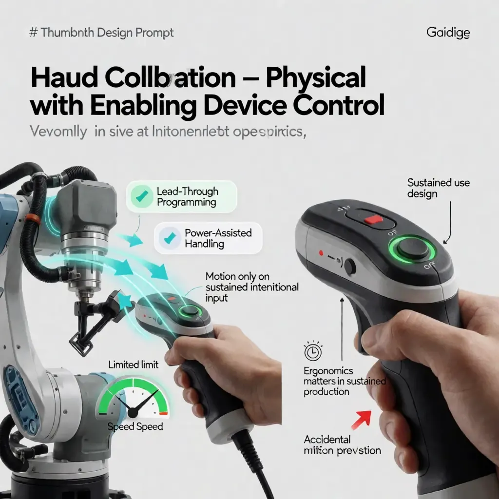 In this collaborative approach, humans physically engage with the robotic arm to pinpoint precise locations or carry out complex procedures. Unlike traditional jogging via teach pendants, hand guiding uses power-assisted handling to amplify the operator's force, making heavy or bulky robots feel light and responsive. However, safety is paramount: motion is only allowed on sustained, intentional input, typically via an enabling device (e.g., a dead-man switch or force/torque sensor thresholds) that must be continuously activated. This prevents accidental motion from bumps or inadvertent contact. The diagram also highlights the importance of ergonomics in sustained production—poorly designed hand-guiding interfaces can lead to operator fatigue or repetitive strain injuries, so optimal handle placement, force scaling, and motion smoothing are critical. Lead-through programming enabled by this mode allows rapid, intuitive path teaching without writing code, significantly reducing setup time for small-batch or frequent-changeover manufacturing lines.
Speed and Separation Monitoring
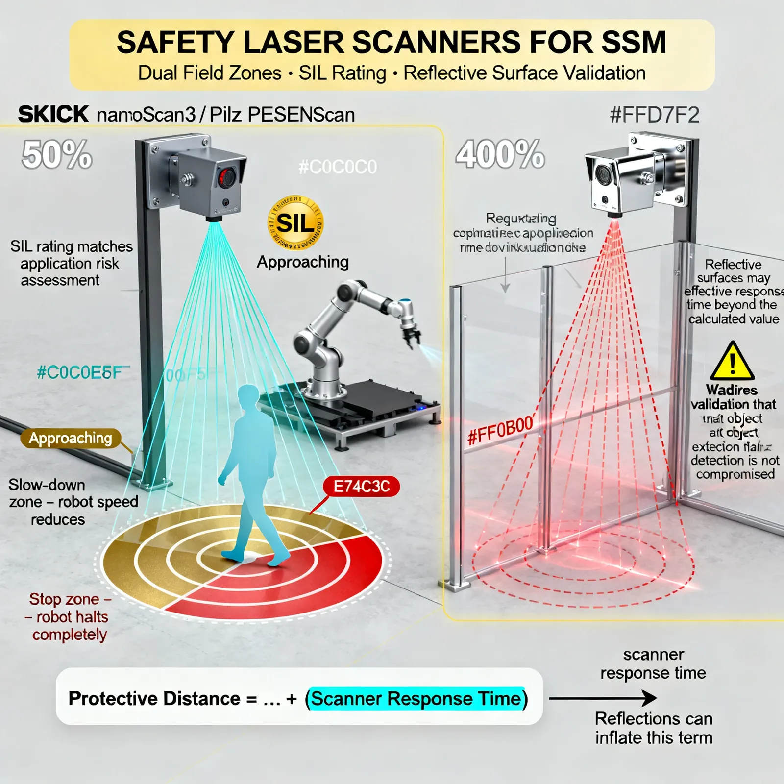
SSM uses external sensors to continuously measure the distance between the robot and detected humans in the cell, scaling robot speed down as the human approaches and triggering a protective stop if the human enters a defined minimum separation distance. SICK nanoScan3 and Pilz PSENscan safety laser scanners are the dominant hardware implementations for this mode in production applications, providing configurable protective field zones with the safety-rated response times SSM requires.
The separation distance calculation is not a simple fixed number. The minimum permissible separation threshold is calculated by taking into account the robot's shutdown interval, set against a baseline human movement speed of 1.6 meters per second, as well as sensor signal processing times and control system noise levels. Getting that calculation wrong by omitting any of those additive terms produces a protective distance that is smaller than required, which means the robot may not be fully stopped before a human arrives at the robot's current position during the stopping sequence. Safety scanner positioning and field geometry relative to all possible approach vectors is the configuration step that most commonly requires revision during validation.
Power and Force Limiting
PFL is the mode that defines most people's mental image of a "fenceless" collaborative robot. To avoid surpassing the biomechanical injury thresholds stipulated by the current version of ISO 10218-2:2025, both kinetic energy and contact force are limited within the confines of Annex A in the latest edition of ISO/TS 15066. ABB GoFa, KUKA LBR iiwa with its integrated joint torque sensors, and Universal Robots e-Series with joint current monitoring all implement PFL, though the underlying sensing and response mechanism differs between these platforms in ways that directly affect validation.
The 2025 standard makes physical force measurement mandatory for PFL compliance validation. Simulation results alone, regardless of how carefully the model is constructed, are no longer accepted as primary evidence. A calibrated Pressure and Force Measuring Device, the IFA hand-arm measurement tool being the standard-referenced example, must be physically applied at each potential contact location in the robot's workspace to measure actual contact forces under real operating conditions. This is a meaningful increase in validation burden, particularly for applications with complex trajectories where multiple contact scenarios need to be measured rather than simulated.
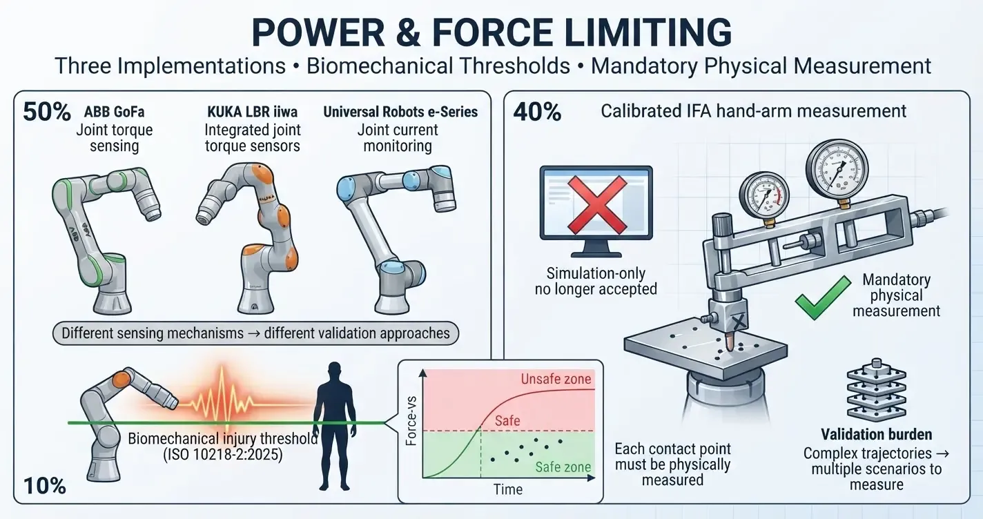 One of the critical safety features built into this robot is power and force limiting, which helps prevent accidents by regulating the robot's energy output and movement speed. The interaction between humans and robots is safeguarded by PFL's commitment to prevent excessive force from being applied. Three commercial implementations are showcased in the diagram, including ABB's GoFa with joint torque sensing, KUKA's LBR iiwa with integrated joint sensors, and Universal Robots' e-Series which utilizes joint current monitoring. Each sensing mechanism has different accuracy, bandwidth, and friction-compensation characteristics, leading to different validation approaches.
Biomechanical Limits: The Numbers and the Logic Behind Them
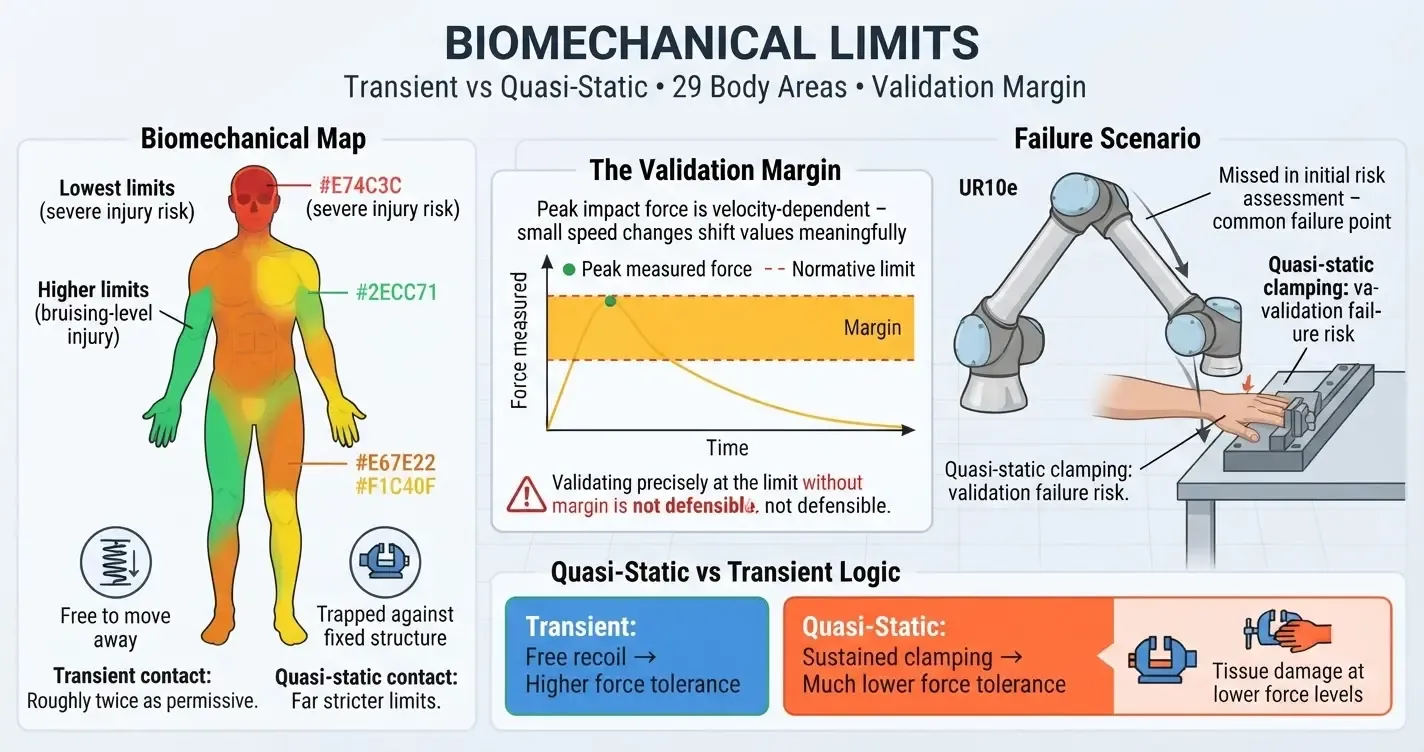
The normative force and pressure limits that PFL applications must stay within are defined across 29 specific body areas and 12 broader body regions, with the skull and temples carrying the lowest limits due to their consequences of injury, and the outer thigh and upper arm carrying higher limits due to both the mechanical properties of that tissue and the reduced functional impact of bruising-level injury there.
The transient versus quasi-static distinction is the most important conceptual nuance in applying these limits correctly. During temporary phases, movement restrictions are relaxed, enabling a greater range of motion for the affected limb compared to static states, where it is restricted to half the amplitude experienced when fully immobile. When an object is stuck between a robot and a stationary surface, sustained pressure typically outweighs brief shocks, causing injury at lower forces than comparable brief impacts. Many PFL validation failures in real applications occur at quasi-static clamping scenarios that the initial hazard identification missed, typically at locations where a robot trajectory passes close to a table edge, frame member, or fixturing that a human hand or arm could be trapped against.
Validating PFL against these limits with a PFMD is labor-intensive but straightforward in principle: apply the measurement device at each identified contact scenario, run the robot at maximum application speed and payload, and confirm that measured peak forces stay within the normative limits with adequate margin. The margin question matters because the PFMD measures peak transient impact force, which is velocity-dependent; small changes in robot speed or approaching mass can shift measured values meaningfully, so validating precisely at the limit without margin is not a defensible compliance posture.
Advanced Sensing Technologies for Collaborative Safety
Six-Axis Force-Torque Sensors
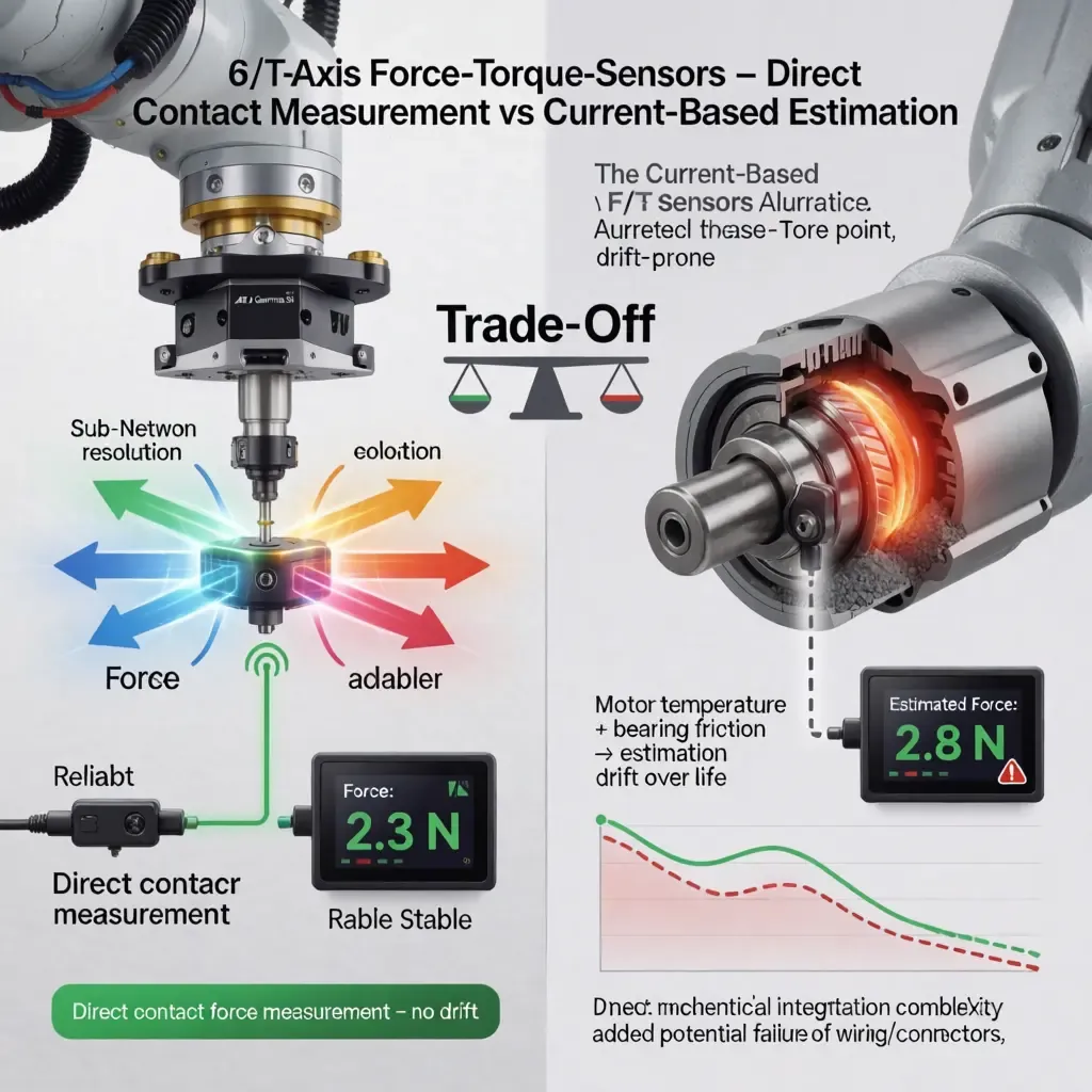
High-resolution 6-axis F/T sensors at the tool flange or integrated into robot joints, ATI Gamma and Gamma SI series being the standard reference hardware in research validation, allow the robot to detect contact across all force and torque axes with sub-Newton resolution. For PFL implementation this provides a direct contact force measurement path that is more reliable than current-based torque estimation, which carries motor temperature and bearing friction variability that degrades force estimation accuracy over the operating life of the joint. The trade-off is cost, mechanical integration complexity at the flange, and the additional wiring and connector that adds a potential failure point.
E-Skin and Advanced Tactile Sensing
Electrical Impedance Tomography applied to compliant conductive skins distributed over robot arm surfaces provides distributed contact sensing at spatial resolutions that discrete sensor arrays cannot match without impractical sensor density. By injecting known current patterns through the conductive skin layer and measuring the resulting voltage distribution, EIT algorithms reconstruct the contact pressure map across the entire sensing area, identifying both the location and magnitude of contact events. Iontronic skins using ion transport in gel matrices as the sensing medium offer self-healing properties that conventional silicone-substrate printed electronics do not, making them considerably more durable under the repeated mechanical stress that robot arm surfaces experience in production environments.
The proximity sensing extension of these e-skin technologies, where the fringe capacitance field beyond the skin surface detects the approaching human hand before physical contact, gives the robot system an anticipatory response capability that allows deceleration to begin before contact rather than after it, which meaningfully reduces peak contact force at the moment of impact compared to systems that detect contact only through force sensing.
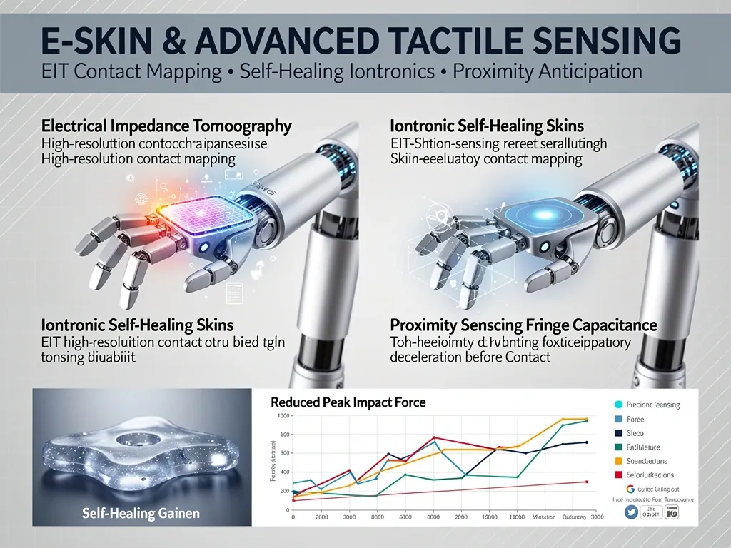 By leveraging cutting-edge e-skin and haptic sensing technologies, this visualization fundamentally alters the landscape of traditional force measurement methodologies. Electrical Impedance Tomography (EIT) enables high‑resolution contact mapping across large, flexible surfaces using fewer electrodes, reconstructing pressure distribution in real time. Iontronic self‑healing skins add robustness by automatically repairing damage from cuts or wear, maintaining sensing performance over long deployments—critical for industrial or prosthetic applications where durability is paramount. The most forward‑looking feature is proximity sensing via fringe capacitance, which detects an approaching object before physical contact occurs. This anticipatory capability allows the robot to initiate pre‑contact deceleration, reducing peak impact force upon interaction. Lower impact forces directly improve safety in human‑robot collaboration and enable gentler handling of fragile objects in picking or assembly. Together, these technologies move tactile sensing from passive contact detection toward proactive, intelligent interaction—bridging the gap between reactive and predictive physical human‑robot interaction.
Safety Laser Scanners for SSM
Safety-rated area scanners for SSM implementation require configuration of at least two protective field zones: an outer slow-down zone where robot speed begins reducing as the human enters, and an inner stop zone where the robot halts completely. The scanner's Safety Integrity Level rating must match the SIL requirement derived from the application's risk assessment, and the scanner's response time is a direct input into the protective separation distance calculation described earlier. Scanner position relative to potential reflective surfaces in the cell, polished metal fixturing and transparent guarding materials being the common problem cases, requires validation that the scanner's object detection is not compromised by those reflective conditions in ways that extend effective response time beyond the value used in the distance calculation.
The functional safety architecture is inherently connected to cybersecurity, as both are essential components of a robust and resilient systems design.
Performance Level and Category Requirements
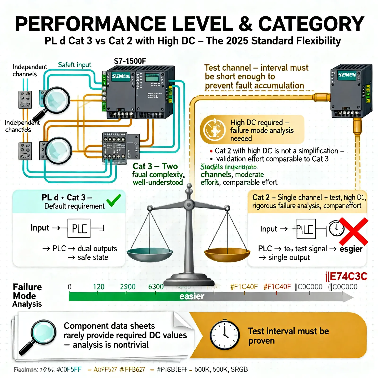
ISO 13849-1 PL d Category 3 has historically been the default architecture requirement for robot safety functions in collaborative applications: two independent safety channels that can each independently achieve the safe state, with diagnostic coverage sufficient to detect a single fault between demands on the safety function. The 2025 standard introduces explicit risk assessment-driven architecture flexibility: if the probability of dangerous failure calculated for a specific safety function is demonstrably low enough, Category 2 single-channel architectures with high diagnostic coverage may be permitted.
This is less permissive than it sounds in practice. Category 2 with high diagnostic coverage requires a test channel that exercises the safety function at intervals short enough that a single-fault-to-dangerous-failure sequence cannot accumulate between tests. Demonstrating that the diagnostic coverage meets the required threshold for the specific hardware used requires detailed failure mode analysis that most standard component data sheets do not provide directly, and the calculation rigor required is comparable to the Category 3 validation effort it nominally simplifies.
IEC 62443 and the Cybersecurity Requirement
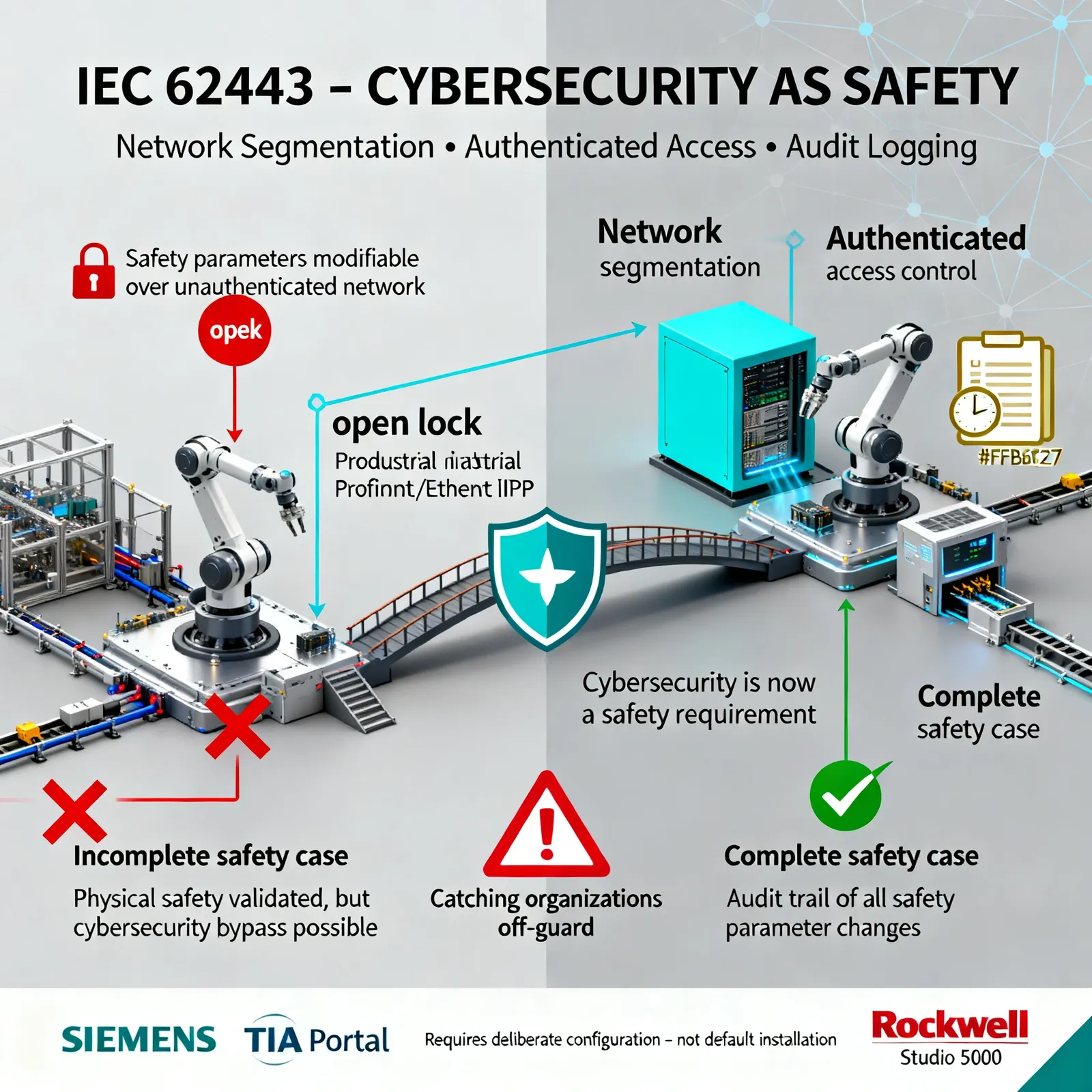
Introducing a new cybersecurity mandate as a compulsory robot safety standard for the very first time will undoubtedly come as a shock to many organizations and pose significant challenges. A networked robot cell where safety parameters can be modified over a network connection that is not appropriately authenticated and segmented does not have a complete safety case under the 2025 standard, regardless of how thoroughly the physical safety functions have been validated.
IEC 62443-3-3 provides the system security requirements framework the standard points toward, covering network segmentation, user authentication for safety parameter access, and audit logging of configuration changes. For a typical robot cell connected to a factory OT network running on Profinet or EtherNet/IP, this means the safety PLC's parameter access must be gated behind authenticated access control, the safety network segment must be isolated from the broader IT network by a properly configured industrial firewall, and configuration changes to safety parameters must be logged in a manner that supports audit trail reconstruction. Implementing this on a Siemens TIA Portal-managed S7-1500F cell or a Rockwell Studio 5000-managed ControlLogix safety system requires deliberate configuration work rather than default installation.
Implementation Discipline: What a Compliant Deployment Actually Requires
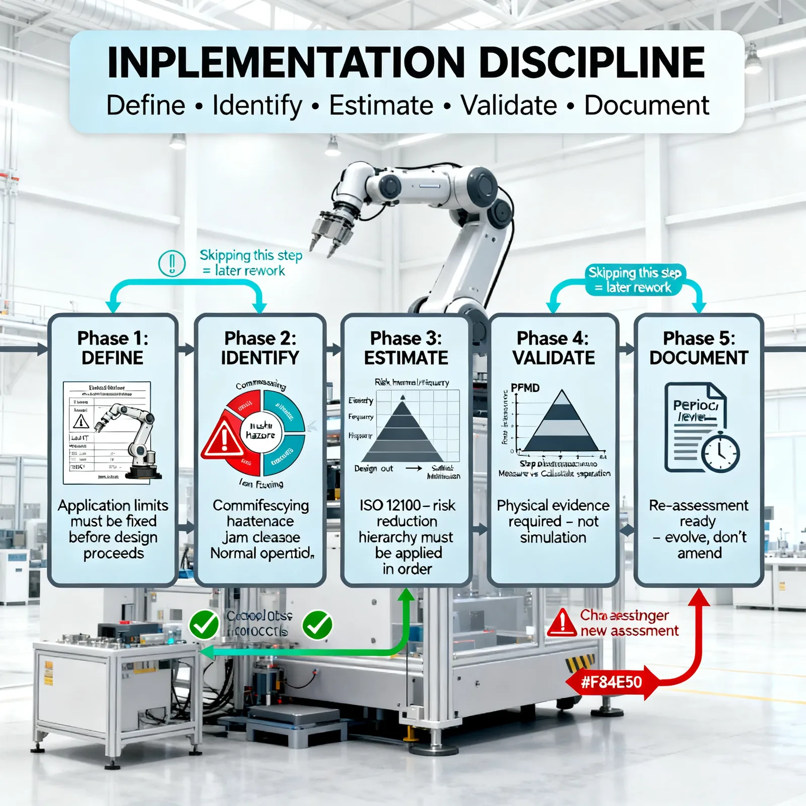
Walking through the implementation sequence is useful because the order matters and skipping steps introduces later rework.
Define the application limits concretely before anything else: robot model, exact EOAT mass and center of gravity, intended payload, maximum speed at each stage of the motion cycle. The safety distance calculations and biomechanical limit margin assessments all depend on these numbers being accurately fixed before the design proceeds.
Hazard identification must span the full lifecycle, not just the steady-state production cycle. Commissioning, programming, maintenance access, cleaning, and jam clearance all expose operators to robot-related hazards in ways the normal operating cycle does not, and the risk assessment must enumerate and address each of them specifically. The crushing hazard introduced by a specific EOAT geometry against a specific fixturing surface is the kind of scenario that hazard identification workshops with experienced operators find reliably and that desk-based assessments routinely miss.
Through the application of ISO 12100 guidelines, quantifying hazards by severity and frequency enables organisations to pinpoint the most pressing threats and opt for targeted mitigation approaches. The risk reduction hierarchy applies in order: engineer the hazard out through design first, add engineering safeguards second, and provide administrative information last. Adding PFL to compensate for a EOAT design that could be made inherently safer is not the correct sequence.
Validation requires physical evidence. For PFL mode, that means PFMD measurements at every identified contact scenario. For SSM mode, that means measured stop distances at maximum speed, confirmed against the calculated protective separation distance with the actual scanner response time, not the data sheet typical value.
Documentation that cannot support periodic re-assessment is incomplete documentation. As the application evolves, as part designs change, as EOAT is modified, the risk assessment needs to be re-executed as a new assessment for the changed application rather than annotated as an amendment to the original.
The Honest Productivity Conversation
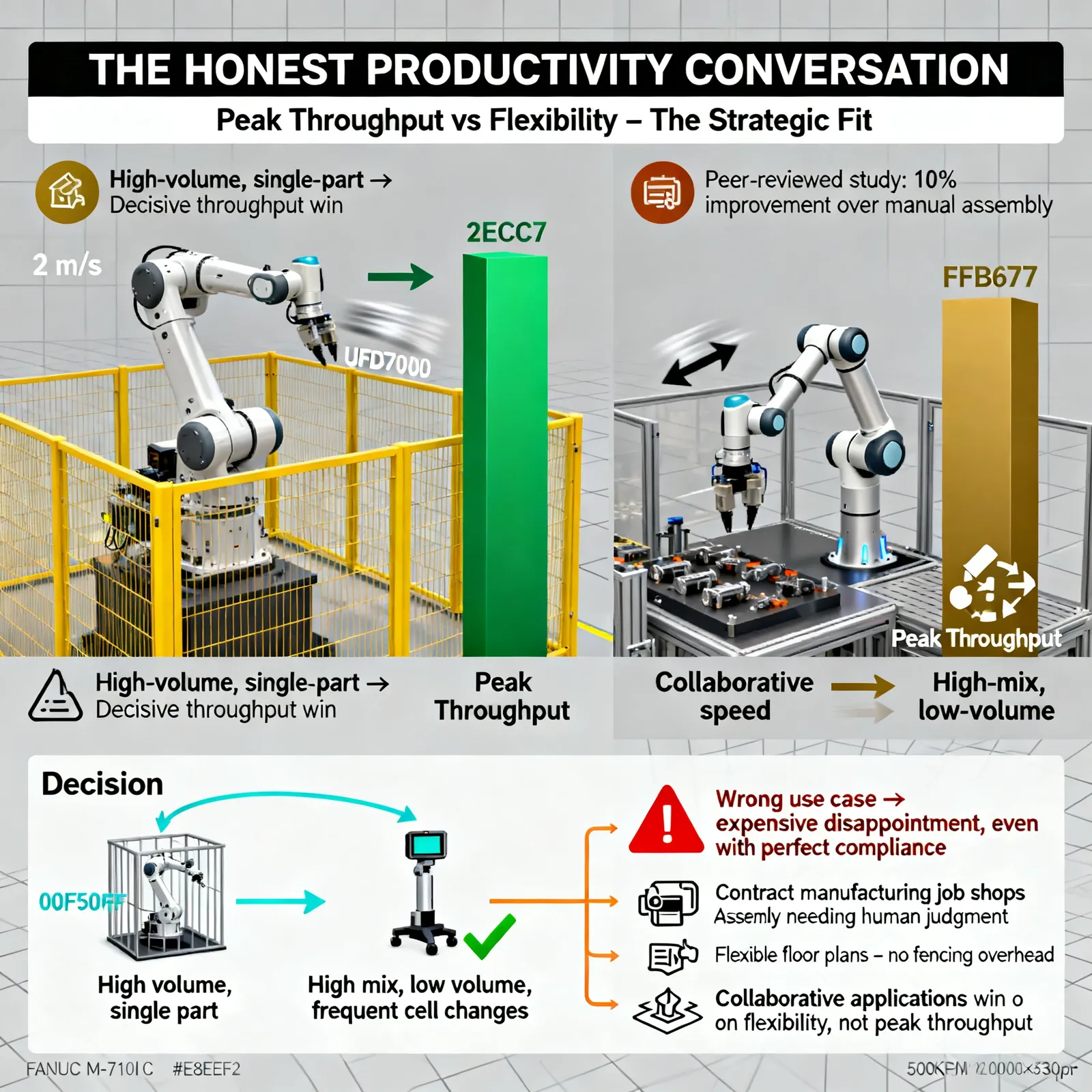
Marketing for collaborative robots frequently implies productivity gains that independent research does not fully support. A peer-reviewed study of cobot deployment in mechanical assembly tasks found a 10 percent productivity improvement over manual assembly. That is a real and economically meaningful gain. It is not the "multiples" improvement sometimes implied in vendor presentations.
The underlying reason is that the same safety limits that make collaborative operation permissible without fencing also constrain operating speed. A traditional industrial robot on a high-volume part in an isolated cell, a FANUC M-710iC running at 2 meters per second behind a safety fence, delivers throughput that a PFL-limited cobot at its safe collaborative speed cannot approach. For high-volume, single-part production, the fenced industrial robot wins decisively on throughput.
Where collaborative applications genuinely win is high-mix, low-volume production: contract manufacturing job shops where the cell configuration changes frequently, assembly lines where human judgment and flexibility on part placement is genuinely needed mid-cycle, and environments where installing and maintaining safety fencing across a flexible floor plan is itself a significant operational overhead. The strategic fit for collaborative applications is defined by that flexibility requirement, not by peak throughput numbers, and specifications built around the wrong use case produce expensive disappointment regardless of compliance quality.
The Practical Upshot
ISO 10218:2025 is the most substantive revision to robot safety standards in over a decade, and the consolidation of ISO/TS 15066's content into the main normative framework means the compliance bar has risen for all collaborative robot applications, not just new ones. The Application-Safety Principle, the mandatory PFMD measurement requirement for PFL, and the new explicit cybersecurity requirement collectively change what a defensible safety case must demonstrate.
For organizations currently operating collaborative applications under the 2011 standard and ISO/TS 15066, a gap assessment against the 2025 requirements is not optional planning; it is the appropriate engineering response to a normative change that affects existing installations. For organizations designing new collaborative cells, building to the 2025 standard from the start is substantially less expensive than validating to the old standard and then remediating the gaps during the transition period.
The underlying engineering principle has not changed: worker protection requires measured evidence, not certified hardware assumptions. The 2025 standard simply makes that principle more precise, more comprehensive, and more enforceable than its predecessor.